Troubleshooting J1939 Multiplexing
The J1939 is a twisted pair of wires in the multiplexing system between modules that communicates using inputs and outputs. Multiplexing can be compared to broadband cable supplying internet access, cable TV and telephone. It sends multiple electronic messages using the same signal path simultaneously with other signals.
The J1939 also known as the backbone is the main data bus for controlling messages and troubleshooting. It operates at high speed between control modules exchanging information back and forth. It consists of a green and yellow twisted pair of wires that is shielded to block interference.
J1939 Module Communication
The bulkhead module on a C2 School bus is the brains of the operation and controls the CHM (chassis hub module) and EHM (expansion hub module) which are slave modules to the BHM. They act on BHM commands turning components on and off and report the status of inputs and outputs.
The J1939 Terminating Resistors
The J1939 has two terminating resistors that are 120 ohms connected in parallel to the data link wiring. A healthy data link circuit resistance will read around 60 ohms at pins C and D at the data link 9 pin connector. The 9 pin connector is where the diagnostic link connects to use diagnostic software on a laptop.
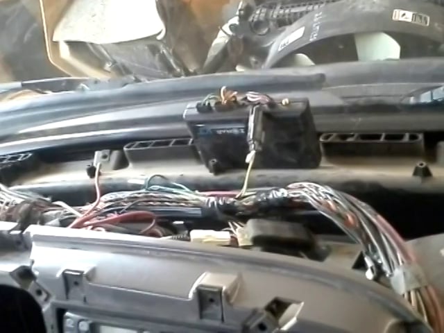
The video shows you where the front terminating resistor is located on the Saf-t-liner C2 School Bus. The second resistor is located at the driver side of the frame close to the drive axle. When you find each resistor it’s handy to check what the resistance is on each one.
There is a formula you can use to determine the exact ohm reading at pins C and D.
If one resistor reading was 118 ohms and the other one was 118 ohms which is not uncommon you multiple those 2 figures. 118 X 118 = 13924
Then you add the 2 together which comes to 236
The next step is to divide both totals into each other. 13924 / 236 = 59 ohms
This gives you an exact resistance to go by when troubleshooting the J1939. One of the resistors could be open or the wiring might be faulty.
This repair will cure a lot of inactive codes that just get erased using diagnostic software. I’m guilty of that as well because of the extra work involved troubleshooting the J1939 wiring. If it’s not reading around 60 ohms there will be a communication breakdown between modules creating codes both active and inactive.
One other important point when doing this procedure on the C2 school bus is you have to disconnect the battery ground. The reason for this is modules communicate on a consistent basis even when the key is off.
Depending on your time frame this is a fussy operation and takes time but it will clear up a lot of confusion within the multiplexing network and get the vehicle back to a proper working order. Please leave a comment below and tell us your experience with this procedure or feel free to ask a question.


