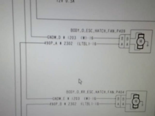
An Example Of A Multiplex Wiring Schematic In the Video below I’m checking Out A Multi-Plex Wiring Circuit On A C2 School Bus. You will see the bulk head module (photo above). It sends and receives inputs and outputs and controls other modules communicating through the J1939 wrg. (You will find more details below) The J1939 is a twisted pair of wires that can send multiple signals at the same time and connected to all of the modules.
What Is Multiplex Wiring
When I first heard the term multiplexing it was very foreign to me. We started getting buses in 2006 with these systems. They were Thomas models and for the most part it was a very efficient way to relay inputs and outputs to run the electrical components on a school bus. I will go over this technology in general and share with you what I know along with my experience on the subject.
The Benefits Of Multiplexing
Our fleet has dozens of Thomas and International school buses that come with multiplex wiring. The benefits of these systems are less wiring to run the electrical system which less chances of electrical wiring failures down the road. The idea is to monitor the entire system using computerized modules.
The instrument cluster in the dash receives information from the onboard computers alerting the drivers of any problems. Freightliner has an online site called Servicelink while International has diagnostic software available which allows a tech to read and diagnose problems.
Thomas Bus Smart Switches
Thomas bus has smart switches which can be added or moved without reprogramming. Switches can be relocated in the dash easily without changing the wiring because the computer recognizes the switch resistance setting. So you could change one switch with another anywhere on the dash. Just plug it in to the existing connector and the module will read the resistance of that switch and know what it controls.
How Multiplexing Works
Similar to cable TV, telephone and internet multiplex wiring allows information to be transmitted through the same wire. The control modules can monitor components along with retrieve and send information. Using signals to do all this requires less relays and connections.
A Multiplexing Example
For example with headlights (Thomas Bus) once the headlight switch is activated the signal goes to the bulkhead module which is the brains of the whole system. Once it receives the switch input it sends the output to the left side headlights while it communicates with a chassis hub module which controls output to the right side headlights. This is programmed so if one module does not work there will always be at least one headlight working.
The communication to all of the modules goes through the J1939 wiring which is the data link. You can have multiple signals to different modules at the same time. Like I pointed out earlier it’s like fibre optics for internet and phone lines transmitting unlimited bits of information in a matter of milliseconds.
One thing that we have found is the wiring and connectors are not full proof when it comes to the environment. If there is corrosion and resistance the computer module signals go haywire in different directions.
Information either does not get to it’s proper destination or it does not arrive at all. We have found several instances where wiring has worn through the loom and caused corrosion and electrical faults.
Troubleshooting
The solution is to hook up the service link on the laptop and see where the circuit has failed or just start wiggling the loom along the frame or tearing the loom off of the wiring harness to physically inspect each and every wire down the line. It’s tedious but necessary.
It does take some time but eventually a fault shows up and the repair is made. Multiplexing is not perfect but it does serve a purpose to minimize wiring and electrical parts along as help us techs find problems faster using troubleshooting software.
If you have experienced multiplexing and want to comment below with your story below please do. Questions are welcome as well thanks for reading this post.


