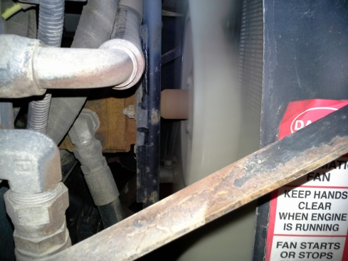
All of the school bus pusher buses have hydraulic drive engine fans. They have their advantages which includes cold start override which cuts down on the engine load and decreases warm up time.
Fan Drive Fault – Staying on Constantly
Right now we have a pusher bus that has an engine fan that stays on at all times. It keeps the engine temperature down to 180 degrees when the engine is warmed up under load but when the bus is coasting the temp drops to 160 degrees.
We are going to check this fault out and repair as necessary. I will be coming back here with a full report when we find the problem. So below I want to share with you an overview of the Parker hydraulic fan drive system. This will give you a better idea what I’m talking about and it also helps me understand the system in more detail.
Parker Hannifin Hydraulic Fan Drive System Overview
The system of choice is manufactured by Parker Hannifin who have developed a system that works well with any diesel engine manufacturer as long as the J1939 communication links up with the fan drive controller (DFC-5).
The J1939 sends all of the engine parameters (coolant and charge air temp) to the controller to help it manage the fan drive properly. The system has a direct engine driven hydraulic pump which is a 2 stage unit for steering and driving the fan motor. Motor in hydraulics means it is being driven. In this case it’s driving the engine fan.
Engine Overheating Hard Steering Complaint
Just wanted to add a tip on these systems. If you experience hard steering and engine overheating most likely you either have a bad hydraulic pump or the controller/manifold valves are not doing their job. We’ve had 2 hydraulic pump failures so far.
Manifold Components
The manifold has valves that direct fluid flow to where it’s needed and sensors to send information back to the controller. The basic system has 2 valves the proportional valve and the priority valve.
Priority Valve – Determines how much flow is directed to the steering system / fan drive and redirects excess oil flow back to the reservoir.
Proportional Valve – Responsible for fan speed and directs oil flow to fan motor or back to the reservoir. This valve is normally closed (No Voltage) with a max pressure of 3,000 P.S.I. For maximum fan speed. With voltage applied the valve opens returning oil back to the reservoir reducing fan speed.
The Digital Fan Controller
The DFC-5 Controller gathers ECU engine data via the J1939 and modulates fan speed for maximum efficiency. Running a direct drive engine fan drains horsepower. With the fan drive modulated horsepower is spared especially with cold (no load) start ups.
How to Get The Software and Comm Cable
To order the software GUI (graphical user interface) there’s a free info CD Part #391-1813-071 which I believe can be ordered through a Freightliner dealer. We get all of our Parker parts through them. They are connected to Thomas Bus Corp and Detroit Diesel.
The RS232 Communication cable for connecting your laptop to the DFC-5 Controller is:
Part # 391-4101-471
Once you get the software and comm cable there are 4 levels of access.
Level 1 – view current operation (no password required)
Level 2 – change parameters up to Parker maximum allowed. (contact Parker for password)
Level 3 – manual control for diagnosis and finding faults. (contact Parker for password)
Level 4 – Parker Authorized personnel only.


