The First Step Troubleshooting Electrical Problems
The last month has been unbelievable with waves of electrical problems. Several International and Thomas buses have been coding, not running and not starting on a steady basis. Corrosion is always the enemy and even though the bus manufacturers try their best to keep electrical harnesses and connections sealed moisture and oxygen and oxygen still does damage.
There are numerous tests to run when troubleshooting electrical problems but the main step before even thinking about what tools are required is the schematic. The wiring diagram is the road map provided by the manufacturer laying out every detail of circuitry on each bus that came from factory. This is information that must be attained first to even have a fighting chance of repairing the wiring issue.
Thomas Pusher HDX Will Not Run
We had a 2007 Thomas pusher bus that would quit on the road and then miraculously start up again. This intermittent scenario is the worst one to repair because you don’t really know if the problem has been fixed. Finally the engine would not run period and it happened at the garage so luck in a way was on our side. The wiring schematic showed one 12 gauge battery wire supplying the engine control module branching off to three 16 gauge wires to a 21 pin connector at the module.
After finding the circuit that supplies battery voltage to the engine control module we grabbed the next best tool for troubleshooting which is the VOM or volt/ohm meter. This makes mechanic life so much easier. We found battery voltage was good at the #12 wire feeding the module but only 6 volts at the 21 pin connector which we unplugged at the engine control module. Somewhere in between there was a bad connection or what is also called a voltage drop 12 volts down to 6 volts.

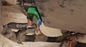
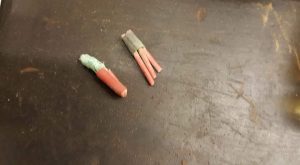
The photo above shows the VEC (vehicle electrical center) located above the engine. The green connector with the heavy gauge red wire is the battery supply. We traced this wire down to the engine control module or MCM (motor control module in Mercedes terms). The VEC tends to corrode over time and we have replaced several of these modules over the years. The next photo below shows the corrosion that has deteriorated the factory splice connection. This condition took 10 years to happen and caused a service call plus several hours of troubleshooting.

The main battery supply shown above used to be connected to the three runners to the MCM. Once the repair was made the engine started up on the first attempt and has been running perfectly ever since. This was a challenge but also a learning experience that will help us out the next time with another bus. The factory connection on these wires were adequate but faltered over time. This just shows that nothing lasts forever.


