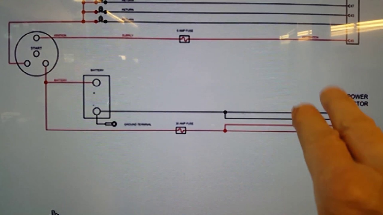
One of our 2009 Cummins ISB diesel engines died on the road today. It doesn’t happen often but unfortunately on the way home the engine shut down like turning off the switch. Two mechanics went downtown to check it out and tried everything they could to get it going. Priming the fuel system didn’t make a difference and the ignition fuse appeared to be alright. The video shows how we look at wiring diagrams. The big screen TV makes viewing electrical schematics much easier on the eyes.
The website I’m using is called Quickserve which is a Cummins site that guides guys like us through the troubleshooting process. Without a wiring diagram you’re blind to starting anything in the right direction. Without a road map you’re going to get lost. The first step to take in this process is to check the source battery power to the engine control module. There is a wire coming from the battery to the ignition switch then to a 5 amp fuse which leads to the other side of the ECM.
As it turns out since the main problem was communication from the ECM to the multiplex wiring system. When poor networking is detected the J1939 system is tested for proper resistance. The resistance must be 60 ohms at the diagnostic plug in terminals but one of my mechanics got a reading of 120 ohms which means an open or faulty resistor. On a similar job I worked on one of the resistors was missing from the plug in. I think once we find the terminating resistor (one at the front and the other at the back) it will be easy to see what failed.
Multiplexing is an informtion highway that sends signals from one module to another. This system can not tolerate corrosion and resistance which leads to circuits operating with the key turned off. Corrosion has a habit of tracking from one terminal to another and making a new circuit sometimes battery power to an accessory. There have been many times I’ve witnessed this condition. For example a door solenoid working on and off after the ignition has been shut down.
This immediate problem can hopefully be resolved when we locate the resistors in the electrical system. On C2 buses there is one resistor under the dash and the other one is close to the expansion modules under the driver side fender. It really depends on the year of the bus on the 2 terminating resistor locations but they are typically at the very front and very back of the bus.
UPDATE: After doing a repair on the J1939 circuit and verifying circuits to the ECM we called Cummins to come over and check the ECM. They could not reboot the ECM so it had to be replaced. How the ECM failed is a mystery but it’s not the first time.


